
X.D. PyMOL Protein–Protein Interface
Julie Himmelberger and Pamela Mertz
Overview: This activity demonstrates how to display interactions at the interface of two macromolecules.
Outcome: The user will be able to display contacts at the interface of two macromolecules and display the non-covalent interactions stabilizing the interface.
Time to complete: 15 minutes
Modeling Skill
- Display contacts at a protein:protein interface
About the Model
PDB ID: 6M0J
Protein: SARS-CoV-2 spike receptor-binding domain bound to the ACE2 receptor
Activity: Angiotensin-converting enzyme 2 (Chain A); Spike protein S1 (Chain B); NAG–glycan; Zn2+; Cl–
Description: Receptor for the pandemic virus, SARS-CoV-2
Steps
Creating an Interface
- In the command line, type: fetch 6M0J, type= pdb1
- In the object/names panel, beside 6M0J, click: A → preset → protein interface
- Create a selection for each protein using the command line:
sele ACE2, chain A
sele spike, chain E
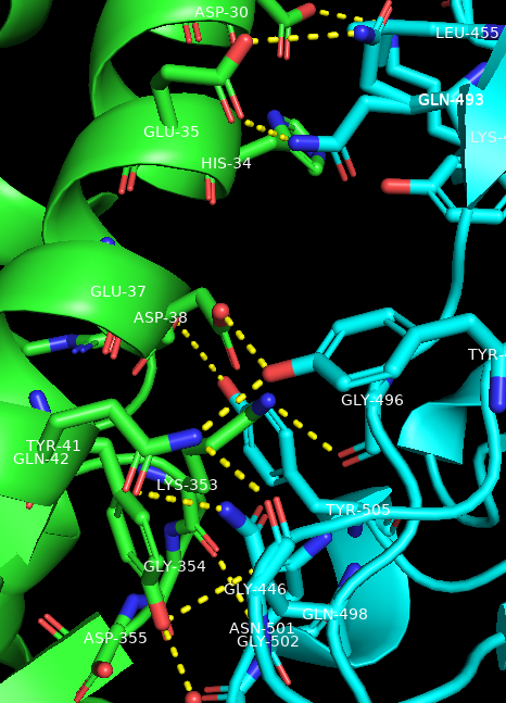
Show the polar contacts between ACE-2 and the spike protein receptor binding domain
- In the names/object panel, click: spike → A → find → polar contacts → to other atoms in object
- Duplicate the object ACE2. In the names/object panel, ACE2→ A → duplicate. Rename the newly made selection to “spike_residues”
- In the names/object panel, click: spike_residues → A → modify → around → residues within 4A
- Duplicate the object spike, and rename it “ACE2_residues”
- In the names/object panel, click: ACE2_residues → A → modify → around → residues within 4A
- Add labels to the amino acid residues on both the ACE2 and spike interfaces. For example, beside spike_residues, click: L → residues
- To make the labels stand out, in the command line, type: set float_label, on
Show a specific interaction between proteins along the interface
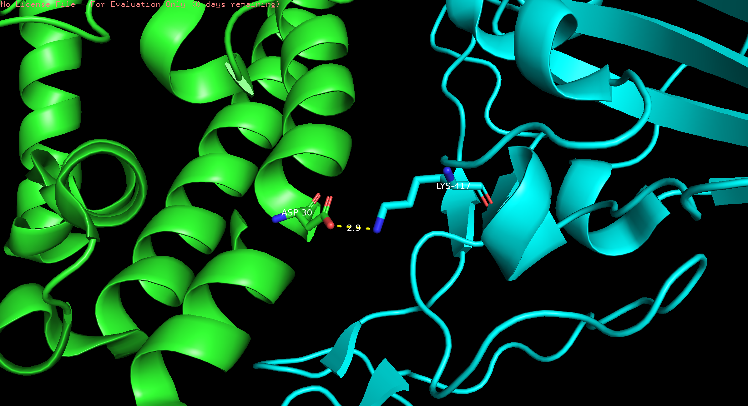
- In the dropdown menu, click Display → Sequence. Select D30 (in chain A) and K417 (in chain E); rename selection to “D30 and K417.”
- In the names/object panel, turn off interactions by clicking on the name “spike_polar_conts.” This will turn off all the yellow dashes.
- In the names/object panel beside 6MOJ, click H –> sticks.
- In the names/object panel, besides spike_residues, click L -> clear. Repeat for ACE2_residues.
- In the names/object panel, click on D30 and K417, S –> sticks. To label these two residues, L -> residues.
- In the dropdown menu, click on Wizard → Measurement. Click on an oxygen atom in the side chain of Asp30 and click on the nitrogen atom in the side chain of K417. This will create a dashed line between the two atoms and give the distance between them.
- Turn off Wizard by clicking on “Done” in the names/object panel under “Measurement.”
- To center, besides D30 and K417, click A -> center.
Show transparent surfaces of ACE2
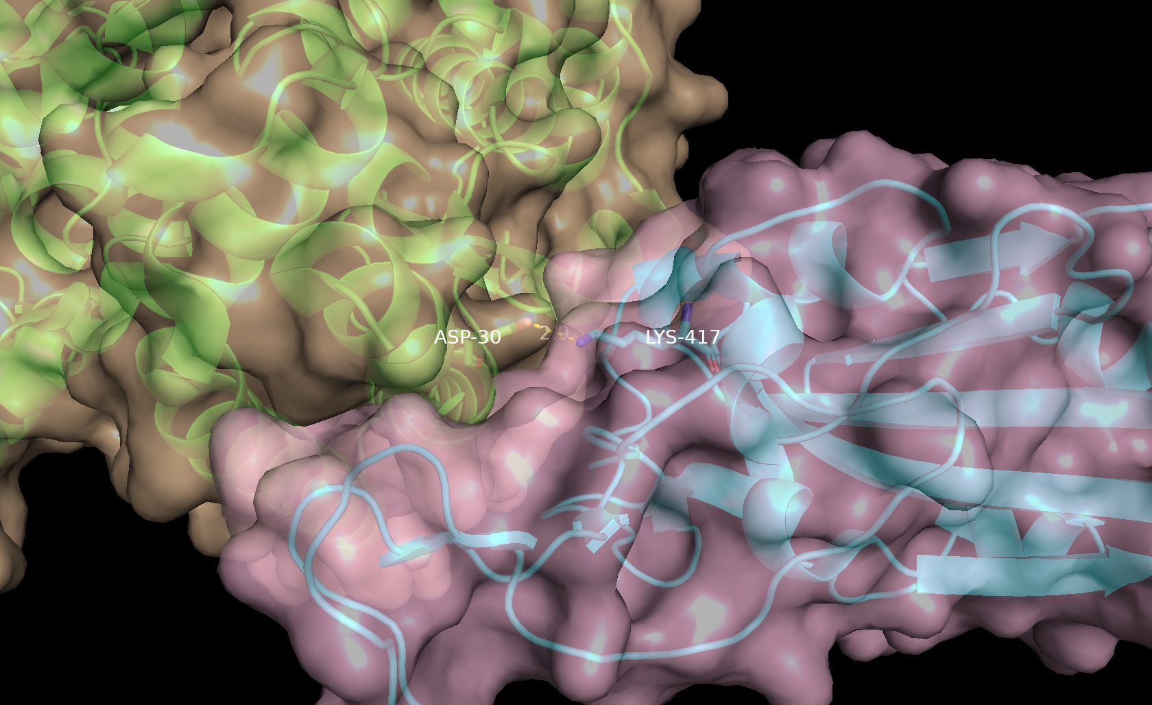
- In the names/objects panel, beside (ACE2), click A → Copy to object → new. Then in the names/object panel rename obj01, click A → rename object and type ACE2_surf.
- In the names/objects panel, beside (spike), click A → Copy to object → new. Then in the names/object panel rename obj01, click A → rename object and type spike_surf.
- In the names/objects panel, beside ACE2_surf, click S → surface. Repeat for spike_surf.
- In the names/objects panel, beside ACE2_surf, click C and select a pale color. Repeat for spike_surf, selecting a different pale color.
- In the command line type: set transparency, 0.3
Note: By creating separate objects for the two proteins, they will be shown as distinct surfaces instead of being displayed as one continuous surface. This also allows us to individually display residues of the proteins using the “color by element” option in the names/object panel.
- To show cartoon representation of the proteins underneath the surface; In the names/objects panel, beside ACE2, click S → Cartoon.
- Repeat the same process for spike.
- To focus in on the interface, In the names/objects panel, D30_and_K147, click A→ zoom.
Note: For visual clarity, select and hide the residues that appear at the interface but do not contribute to polar interactions. ACE2 → H → everything, spike → H → everything. Re-show your labels for the spike_residues and ACE2_residues.
Click here to go to Chapter XI: Superimposition